Proportional Adjustment Needle Valve SD-NV-A10
Proportional Control Needle Valve SD-NV-A10
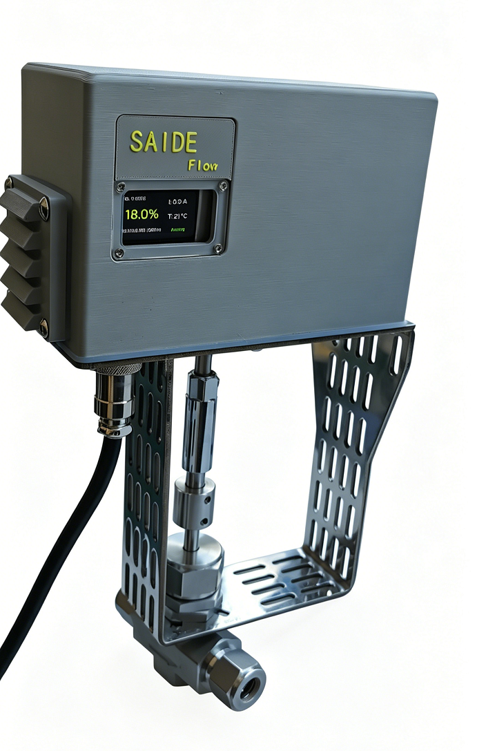
Application Scope
Remote control of industrial fluids, applicable media include water, chemical fluids, hydraulic oil, gases, etc.
Product Features
-
Analog signal control and analog signal feedback
-
Key parameter display on screen
-
LAN viewing and control available
-
Can execute automatic cycles with customizable signal variation patterns.
-
Open-loop or self-closed-loop mode, freely switchable
-
Pressure up to 5000psi
-
Operating Temperature:
PTFE: -54°C to 232°C (-65°F to 450°F) PEEK: -54°C to 316°C (-65°F to 600°F)
-
Wide range of applicable media: Media contact materials are 316 stainless steel and sealing materials PTFE or PEEK
-
Optional positive pressure explosion-proof measures (no explosion-proof certificate).
Rated Parameters
| Item | Technical Parameter |
|---|---|
| Rated Voltage | 24V/DC |
| Analog Input | 4-20mA (default), 0-5V, 0-10V, 0-20mA |
| Spool Position Feedback | Opening 0%-100% corresponding feedback: 4-20mA/0-20mA (default), 0-5V/0-10V |
| Maximum Working Pressure | 345 bar (5000 psig) |
| Applicable Media | Water, chemical fluids, hydraulic oil, gases |
| Weight | 2.4 kg |
| Overall Dimensions | 320mm * 175mm * 90mm |
| Protection | Over-temperature protection, overload protection |
| Media Temperature | -60 to +350°C |
| Ambient Temperature | -20 to +70°C |
📊 Key Technical Indicators Comparison Table for Open/Closed Loop
Users can select open-loop or self-closed-loop control mode in the parameter settings. The advantages and disadvantages are as follows:
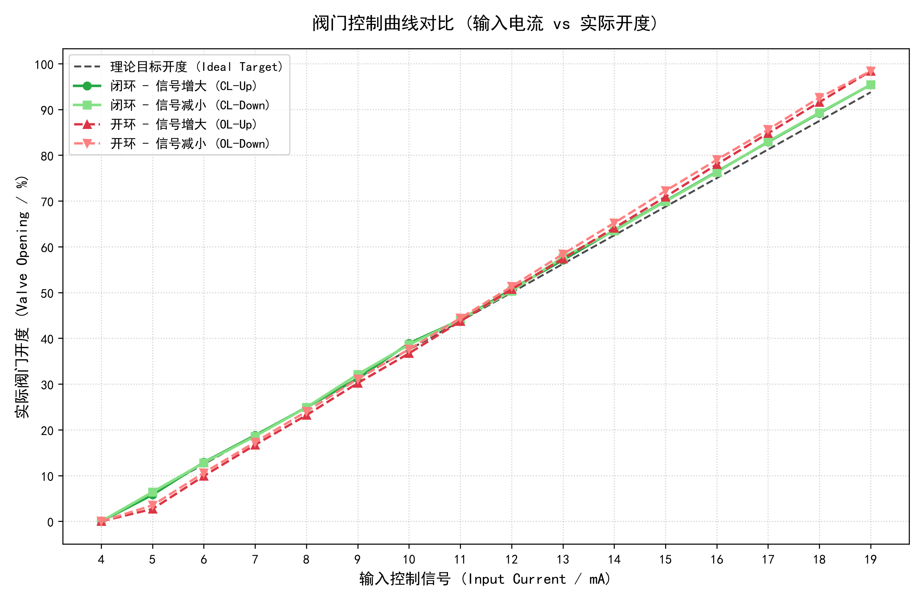
Open-loop mode: The valve runs continuously and reaches the position in one step without callback action. The disadvantage is that its performance exhibits S-type non-linearity.
Closed-loop mode: The valve adjusts in small steps. It may produce small callback actions, but the non-linearity is significantly better than in the open-loop mode. For specific comparisons, see the diagram and table below.
Comparison Table of Error and Hysteresis Data
| Analysis Dimension | Closed-Loop Mode (Closed-Loop) | Open-Loop Mode (Open-Loop) | Remarks |
|---|---|---|---|
| Max Positioning Error | $\pm 1.80%$ | $\pm 5.10%$ | |
| Max Hysteresis | $0.90%$ | $1.3%$ | |
| Average Hysteresis | $0.22%$ | $0.76%$ |
Selection Guide
Complete example model: SD-NV-I2-SS-V1-S8-10
Default feedback signal is consistent with control signal; if inconsistent, please specify when ordering.
| Annotation | Code | Technical Parameter |
|---|---|---|
| Saide Code | SD | |
| Needle Valve | NV | |
| Control Signal | I2 | I1 - 0-20mA I2 - 4-20mA (default) V1 - 0-5V V2 - 0-10V |
| Feedback Signal | N | I1 - 0-20mA I2 - 4-20mA (default) V1 - 0-5V V2 - 0-10V N - No Feedback |
| Valve Material | SS | 316 Stainless Steel |
| Valve Series | V1 | V1 Series |
| Fluid Form | - Straight-through type A - Right-angle type |
|
| Interface Type | S8 | Nominal Diameter 6 S6 - Double ferrule, 3/8 inch imperial tube SM12 - Double ferrule, 12mm metric tube FR6 - Internal thread G3/8 F6 - Internal thread NPT3/8 Nominal Diameter 10 S8 - Double ferrule, 1/2 inch imperial tube SM14 - Double ferrule, 14mm metric tube FR8 - Internal thread G1/2 F8 - Internal thread NPT1/2 |
| Valve Nominal Diameter | 10 | 6 - 6.4mm Cv value: 0.73 10 - 9.5mm Cv value: 1.8 |
| Spool Type | - V-type 11b - Regulating type 11c - Soft-sealed spool (PTFE and PEEK optional) 11d - Non-rotating spool |
|
| Packing | - PTFE P - PEEK |
Overall Dimensions
Actuator Dimensions
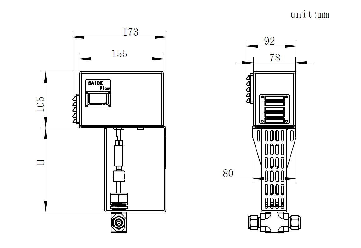
| Nominal Diameter | H |
|---|---|
| 6 | 132.2 |
| 8 | 155.8 |
Needle Valve Dimensions
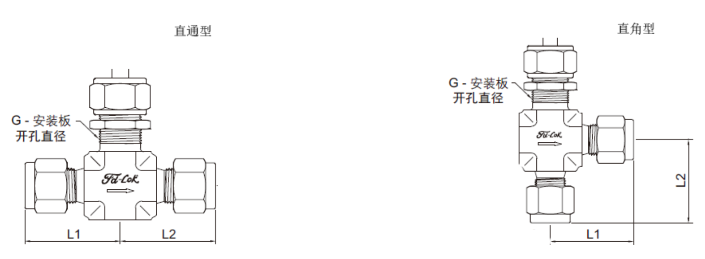
| Basic Information | Interface Type | Internal Diameter (mm) | Cv | L1 (mm) | L2 (mm) |
|---|---|---|---|---|---|
| -V1-S6-6 | Double ferrule, 3/8 inch imperial tube | 6.4 | 0.73 | 32.8 | 32.8 |
| -V1-SM12-6 | Double ferrule, 12mm metric tube | 6.4 | 0.73 | 35.6 | 35.6 |
| -V1-FR6-6 | Internal thread, G3/8 | 6.4 | 0.73 | 26.9 | 26.9 |
| -V1-S8-10 | Double ferrule, 1/2 inch imperial tube | 9.5 | 1.80 | 48.3 | 48.3 |
| -V1-SM14-10 | Double ferrule, 14mm metric tube | 9.5 | 1.80 | 48.3 | 48.3 |
| -V1-FR8-10 | Internal thread, G1/2 | 9.5 | 1.80 | 38.1 | 38.1 |
Spool Type and Material Structure
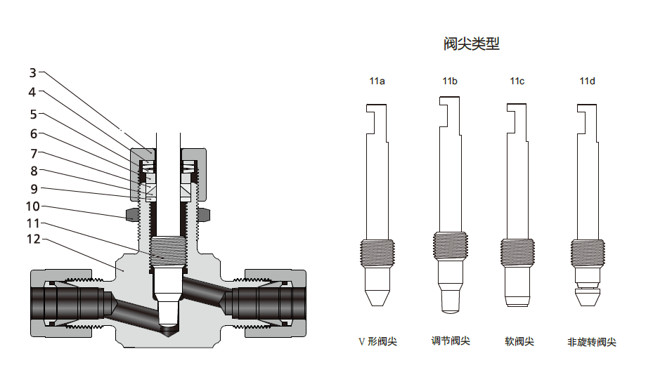
| Serial No. | Component | 316 Stainless Steel Material |
|---|---|---|
| 3 | Gland Nut | 316 SS/A276 |
| 4 | Pressure Ring | 304 SS/A276 |
| 5 | Spring | S17700/A693 |
| 6 | Packing Gland | 304 SS/A276 |
| 7 | Upper Packing | PTFE / PCTFE / PEEK |
| 8 | Lower Packing | PTFE / PCTFE / PEEK |
| 9 | Lower Packing Ring | 316 SS/A276 |
| 10 | Panel Nut | 316 SS/B783 |
| 11 | Valve Stem | Chrome-plated 316 SS/A276 |
| 12 | Valve Body | 316 SS/A182 |
| - | Lubricant | Molybdenum Disulfide |
Wiring Instructions
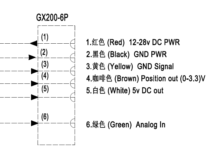
Screen Display
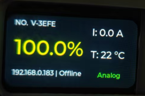
| NO. V-3EFE | Valve No.: V-3EFE | 91.3% | Current valve opening |
|---|---|---|---|
| T:26.4℃ | Current temperature of drive motor | ||
| 192.168.4.1 | Hotspot IP (fixed) | 192.168.0.184 | LAN IP after network configuration (depending on user environment) |
| off | No device connected, automatically turn off Wi-Fi function When the device restarts, Wi-Fi function will automatically turn on, if there is no device connected, it remains on for 3 minutes before turning off. |
Analog | Current control mode is Analog |
Network Configuration & Control
Built-in Wi-Fi hotspot (can be disabled or hidden), default hotspot: Saide_Valve NO.(V-3EFE)
After connecting to the hotspot, use a browser to access IP: 192.168.4.1. The interface is shown below. If there is a wireless LAN in the environment, it is recommended to prioritize network configuration settings. Joining the LAN provides much higher connection reliability.
Every time the device boots up, it will automatically enable the AP hotspot. If no connection is made within 3 minutes, the hotspot will automatically close. Once network configuration is successful, the device will automatically join the LAN upon next startup and display its IP address on the screen:
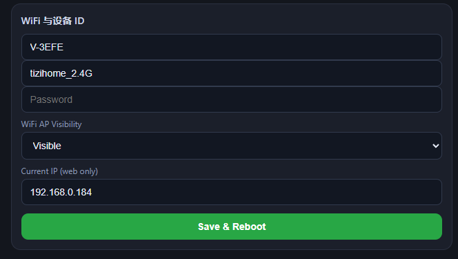
Enter the Wi-Fi name and password of the LAN, save and restart to complete the network configuration.
Web Console
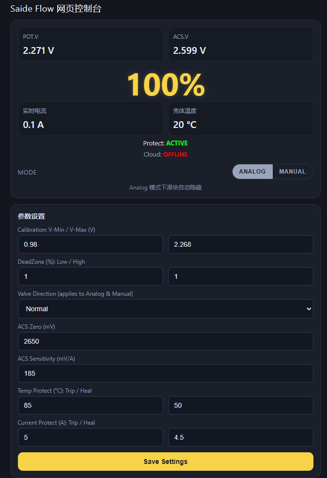
| POT.V | Valve position voltage | Housing Temp | Valve actuator motor housing temperature, mainly for over-temperature protection function |
|---|---|---|---|
| Protect: ACTIVE | Valve status: Normal | ||
| ANALOG | Control mode: Analog | MANUAL | Control mode: Manual When switched to manual mode, valve opening can be adjusted via the slider on the web page |
The valve can enable automatic cycle control mode, and the signal variation relationship can be defined:
| Cycle Count | Set the required number of cycles | Current Progress | How many cycles have been executed currently |
|---|---|---|---|
| Target Opening | Valve opening per cycle | Time | Signal duration time |
| Signal Relation | Step or linear change | Add Cycle Step | Add next position point |
Parameter Settings
Parameter settings require unlocking to set or modify. Default unlock password: abc123
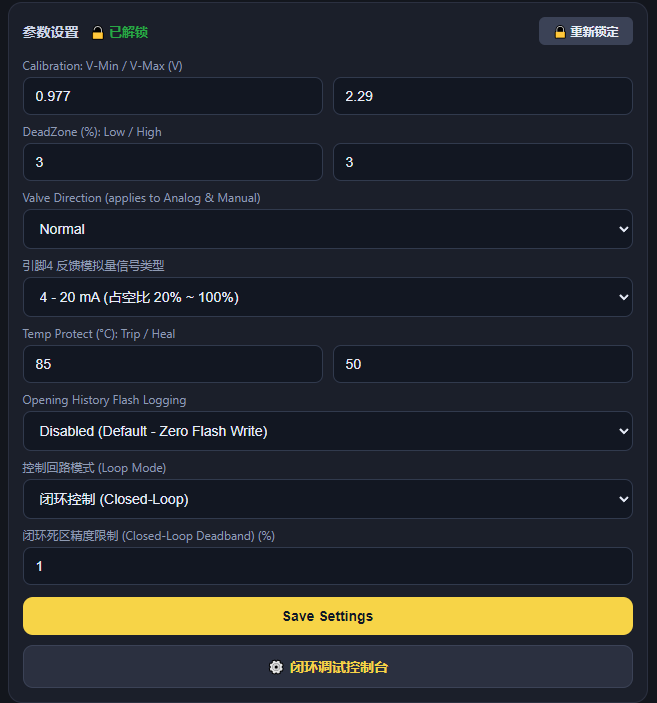
| Calibration: V-Min / V-Max (V) | Corresponding POT.V voltage values when valve is closed and fully open | DeadZone (%): Low / High | Valve dead zone percentage settings |
|---|---|---|---|
| Valve Direction (applies to Analog & Manual) | Direction setting of signal direction and valve position | Feedback Analog Signal Type | Select feedback analog signal type. Only the same signal category can be selected: if factory feedback is current type, it can only switch between current types; if factory feedback is voltage type, it can only switch between voltage types. |
| Temp Protect (°C): Trip / Heal | Protection temperature trip and recovery values | Opening History Flash Logging | Valve opening history logging (disabled by default) |
| Loop Mode | Open-loop or closed-loop control | Closed-Loop Deadband (%) | Stops once closed-loop control is within the permitted accuracy percentage range. |
Opening Data Interface
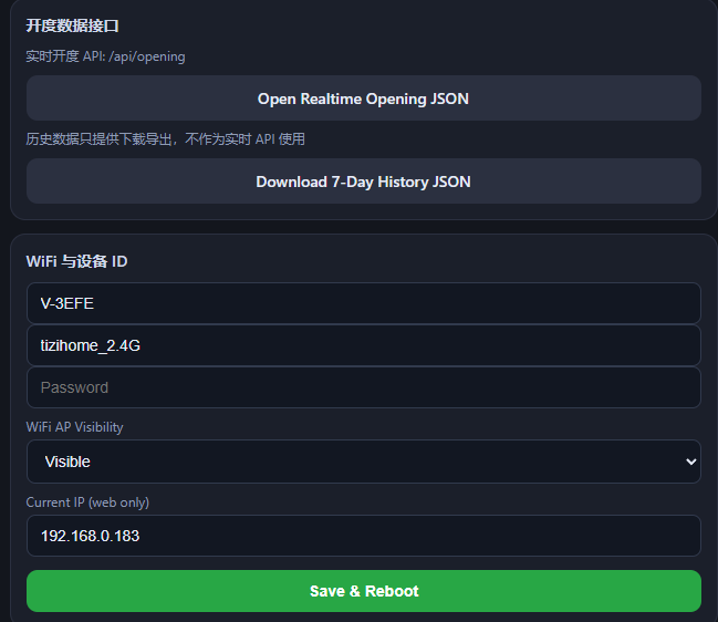
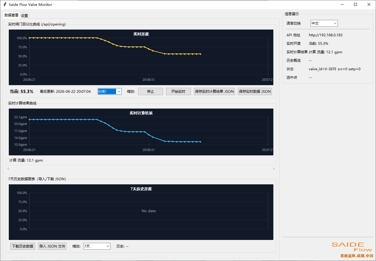
The actuator can store 7 days of opening data, which can be exported and saved here. You can also use the software provided by us, valve_monitor_app.exe, to enter the relationship between valve opening and Cv value or valve opening and pressure, calculating physical quantity changes in real time:
Network Configuration Settings
Fill in the LAN Wi-Fi name and password, click Save and Restart. The device will automatically obtain a LAN IP address and display it on the screen or web page. In this way, there is no need to connect to the device's hotspot later, and you can freely access the same page via the IP assigned by the LAN.
You can set whether the Wi-Fi hotspot is hidden;
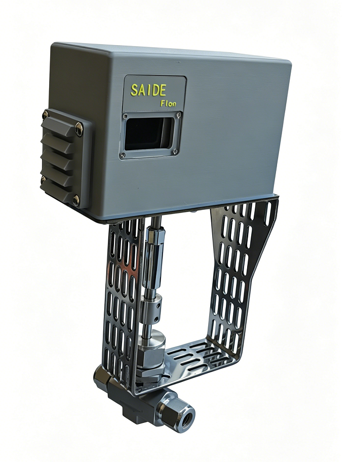
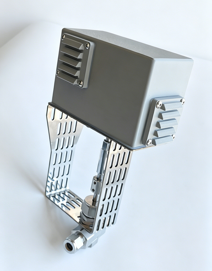
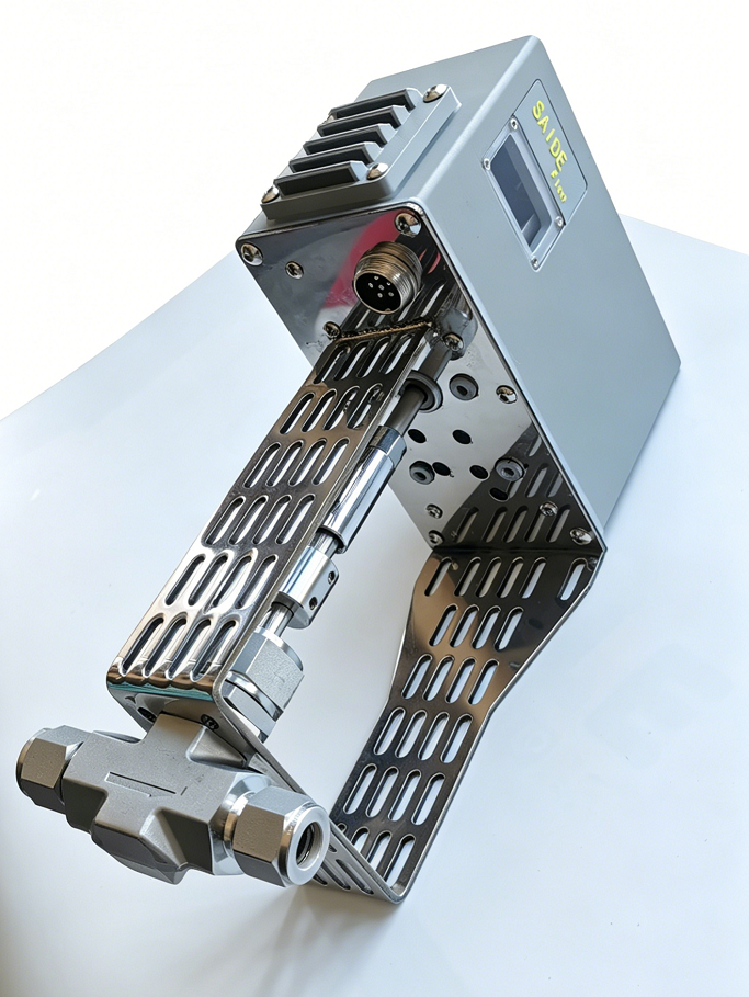
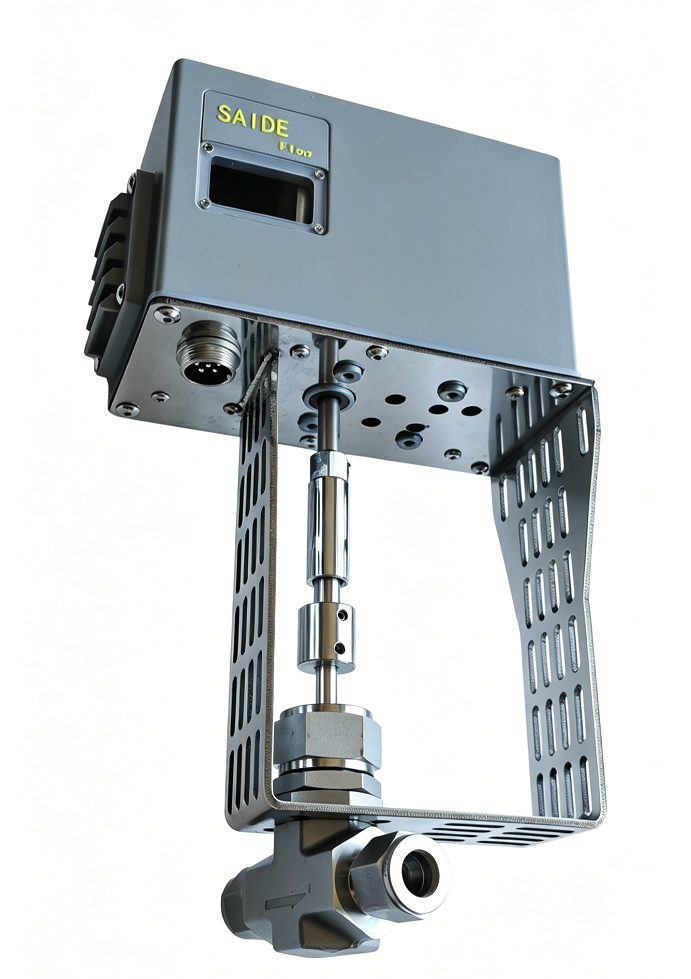
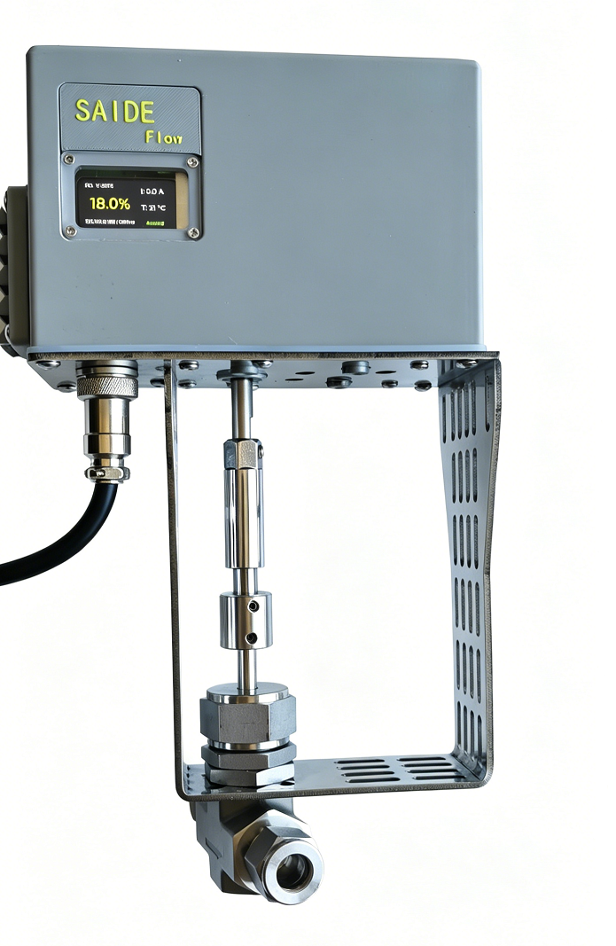
Physical Pictures
|
 |
 |
|---|---|---|
 |
 |
 |