PT100/PT1000 RTD, 2-Channel Temperature Module Modbus RTU 485
1. Product Overview
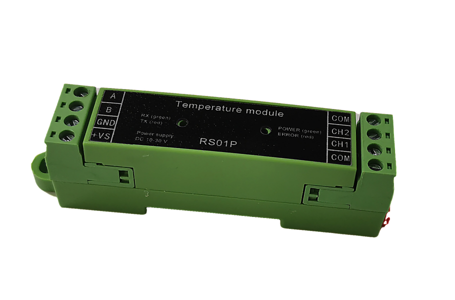
The RS01P is an industrial temperature transmitter based on RS485 communication, designed specifically for connecting PT100 or PT1000 platinum resistance temperature detectors (RTDs). It uses the standard MODBUS-RTU protocol and is suitable for precise temperature measurement in industrial automation, environmental monitoring, and similar applications.
2. Application Fields
- Industrial process temperature measurement
- Warehouse and greenhouse environmental monitoring
- Constant temperature equipment (e.g., refrigerators, cold storage)
- Water temperature measurement
- Other ambient temperature measurement scenarios
3. Hardware Specifications
| Item | Specification |
|---|---|
| Communication Interface | 1x RS485 |
| Sensor Type | PT100 / PT1000 (Supports 2 channels of 2-wire RTD input) |
| Power Isolation | Sensor is isolated from power supply; RS485 is not isolated from power supply |
| Protection | RS485 and sensor input interfaces are protected with TVS diodes |
| Indicator Function | LED for operational status and communication activity |
| Power Supply Voltage | DC 7V - 30V |
| Resolution | 0.01°C |
| Product Dimensions | 98mm × 20mm × 27mm (L×W×H) |
4. Communication Protocol
- Protocol: MODBUS-RTU (Custom protocols available upon request)
- Default Settings:
- Baud Rate: 9600 bps
- Data Bits: 8 bits
- Stop Bits: 1 bit
- Parity: None
- Configurable Ranges:
- Baud Rate: 1200 ~ 115200 bps
- Stop Bits: 1, 1.5, 2
- Parity: None, Odd, Even
5. Key Performance Parameters
| Parameter | Min | Typ | Max | Unit | Remarks |
|---|---|---|---|---|---|
| Supply Voltage | 7 | — | 30 | VDC | — |
| Measurement Accuracy | — | ±0.1 | — | °C | At 25°C |
| Conversion Speed | — | 5 | — | readings/sec | All channels |
| Stability | — | ±0.02 | — | °C | At 25°C |
| Operating Temperature | -40 | — | 70 | °C | — |
| Supply Current | — | — | 40 | mA | At DC 12V input |
| Max Units on Bus | — | 32 | — | units | Without repeaters |
| Address Range | 1 | — | 254 | — | 0 is broadcast address |
| Calibration Offset | -12.8 | — | 12.7 | °C | — |
Notes:
- A power cycle is required for baud rate changes to take effect.
- When multiple devices are connected on the same bus, each station address must be unique.
- Default station address is 1.
6. MODBUS Register Map (RS01P Specific)
All temperature values are signed integers. Units are 0.01°C (unless otherwise noted).
| Register Address (Decimal) | Corresponding Function (R/W) | Data Description / Example |
|---|---|---|
| 0 ~ 1 | Channel 1 & 2 Temperature Value (0.1°C) (R) | (Read Value) × 0.1 = Actual Temperature (°C) |
| 30 | Device Address (R/W) | Range: 1-254 (Factory Default: 1) |
| 31 | Baud Rate (R/W) | Value Mapping: 0=300, 5=9600, 11=115200 |
| 34 | Stop Bits (R/W) | 0=1 bit, 1=1.5 bits, 2=2 bits |
| 35 | Parity (R/W) | 0=None, 1=Odd, 2=Even |
| 220 | Sensor Type (R/W) | 0 = PT100, 1 = PT1000 |
| 680 ~ 681 | Channel 1 & 2 Temperature Value (0.01°C) (R) | (Read Value) × 0.01 = Actual Temperature (°C) |
| 500 ~ 501 | Channel 1 & 2 Temperature Offset Calibration (R/W) | Range: -1280~ 1270 (Corresponding to -12.8°C ~ +12.7°C) |
Explanation:
- Register addresses are based on the MODBUS protocol. In some systems (e.g., PLCs, SCADA), addresses may need mapping (e.g., Register 0 corresponds to holding register 40001).
- "R" indicates Read-Only, "R/W" indicates Read/Write.
7. Baud Rate Value Mapping Table
| Setting Value | Actual Baud Rate |
|---|---|
| 0 | 300 |
| 1 | 600 |
| 2 | 1200 |
| 3 | 2400 |
| 4 | 4800 |
| 5 | 9600 (Factory Default) |
| 6 | 19200 |
| 7 | 38400 |
| 8 | 43000 |
| 9 | 56000 |
| 10 | 57600 |
| 11 | 115200 |
8. Usage and Configuration Guide
- Initial Connection: The factory default device address is 1. Connect the device to a PC via a USB-to-RS485 converter.
- Address Modification: When multiple devices are used on the same bus, each device must be assigned a unique station address. The broadcast address (0) can be used for initial discovery and setup, but only when a single device is online.
- Software Configuration: It is recommended to use the manufacturer's free configuration software for parameter setting (address, baud rate, sensor type, offset calibration, etc.).
- Sensor Connection: Ensure PT100/PT1000 sensors are correctly connected to the designated 2-wire input terminals for each channel.
- Parameter Activation: After modifying Baud Rate or Sensor Type, a device restart (power cycle) is mandatory for the new settings to take effect.
9. Communication Command Examples (MODBUS-RTU Based)
Below are example hexadecimal command frames for common operations (assuming current device address is 1; response frame address will be the set address).
| Operation | Send Command (Hex) | Response Example (Hex) | Explanation |
|---|---|---|---|
| Find Slave Address | 00 03 00 1E 00 01 E5 DD | 02 03 02 00 02 7D 85 | Found device at address 02 |
| Change Slave Address to 02 | 00 06 00 1E 00 02 69 DC | 00 06 00 1E 00 02 69 DC | Address changed successfully |
| Read Channel 1 Temp (0.01°C) | 00 03 02 98 00 01 C4 32 | 02 03 02 00 CF BC 10 | Temp Value: 0x00CF = 207 => 20.7°C |
| Set Sensor Type to PT100 | 00 06 00 DC 00 00 49 E1 | 00 06 00 DC 00 00 49 E1 | Set successfully |
| Set Sensor Type to PT1000 | 00 06 00 DC 00 01 88 21 | 00 06 00 DC 00 01 88 21 | Set successfully |
| Set Channel 1 Offset (+5.00°C) | 00 06 02 F8 00 32 89 87 | 00 06 02 F8 00 32 89 87 | Offset: 0x0032 = 50 => +5.00°C |
| Read 2-channel temperature (°C) | 00 03 00 28 00 02 45 D2 | 02 03 04 F8 00 01 44 F9 F0 |
10. Important Notes
- Do not operate registers not defined in the register map.
- Ensure a 120Ω termination resistor is connected at the end of the bus to reduce signal reflection.
- The device has reverse polarity protection, but correct power polarity should still be observed.
- For technical support or custom protocol requests, please contact the manufacturer.